FIRE PUMP TEST PIT · ENGINEERING EXPLORERCAL FIRE Shasta Trinity Headquarters · A2.214 study prototype
Interactive engineering visualization · prototype v0.8

Two criteria. One clear design check.

Review air removal by Wall 2 and the calculated average water velocity in Chamber 3. The water level, fixed structure and all calculations share one Z-up coordinate model. Supporting hydraulics remain below the 3D view.

Review scope: an engineering screening tool, not validated CFD. Air-removal PASS requires documented, reviewer-confirmed assumptions. A low bulk velocity does not prove low local jet or suction velocity.
PRIMARY REVIEW CRITERIA

DESIGN CHECK

COMBINED RESULTNOT VERIFIED
01

AIR REMOVAL — By Wall 2

NOT VERIFIED

Document the air-removal assumptions.

Conservative buoyancy / residence-time screen in Chamber 2 only. No credit for removal in Chamber 1. Not a measured air fraction or a guarantee of complete de-aeration.
02

CHAMBER 3 VELOCITY

—

— fps ≤ 0.50 fps

Calculated Average Velocity — Chamber 3
Bulk flow through the flooded transverse section after Wall 2.
00.50 fps limit
V₃ = Q / A₃, with A₃ = clear width × water depth × net-area factor. Not a Wall 2 opening velocity, local maximum, or strainer approach velocity.
Air-removal calculation basis & reviewer inputs EXAMPLE INPUTS — NOT VALIDATED

A checked box records reviewer input; it is not independent verification by this software. PASS means the two stated screening checks pass under that basis. Empty, invalid or unreviewed air inputs cannot produce an overall PASS. Changes to the air assumptions clear the acknowledgement.

↑ +Z / UP   •   GRADE = 0.00 ft
A2.214 STUDY · v0.8 · UNIFIED Z-UP
Q = 1500 GPM
NET V = 19,363 GAL
FLOW FIELD · ILLUSTRATIVE
water tracersair / buoyancy cuesILLUSTRATIVE MOTION · NOT CFD
Chamber 1 = upstreamChamber 2 = middleChamber 3 = downstream of Wall 2
Water level — fixed sectionWalls / grade / floor do not move with this slider.

Supporting calculations not substitutes for the two primary criteria

Baffle hydraulics
0.42 / 0.19 fps
Average opening velocity through Wall 1 / Wall 2. The arithmetic is useful, but does not demonstrate “100% de-aeration.”
V = Q / A · A₁=8 sf · A₂=18 sf
Residence time
12.83 min
C1 3.03 · C2 3.31 · C3 6.48 min
t = chamber volume / flow
6 in suction screening
8.51 fps / hose
Two hoses selected. Actual adequacy requires the apparatus, hose, strainer and pump manufacturer data.
Vs = Q / [n · πD²/4]
Pit turnover
12.91 min
Approx. 1.55 full-pit turnovers during a 20-minute rated-capacity run.
turnover = net usable volume / flow
Design envelope

Usable water ratio across pump flow

Live comparison of Current, Floor −1 ft, and Bay +2 ft geometry at the selected water-surface elevation. The dashed threshold is the 10 gal/GPM criterion used by the source calculation document — not presented here as an NFPA requirement.
CurrentFloor −1 ftBay +2 ft10 gal/GPM source criterion
Scenario comparison

Same operating point · different geometry

ScenarioNet galgal/GPMSubm.
Decision 1Confirm the formal Design Apparatus Schedule and maximum required flow before resizing the vault.
Decision 2If 2,000 GPM is retained, compare depth, length and water-level options with structural/civil impacts.
Decision 3Define suction and flow measurement hardware before treating the pit as a complete test system.
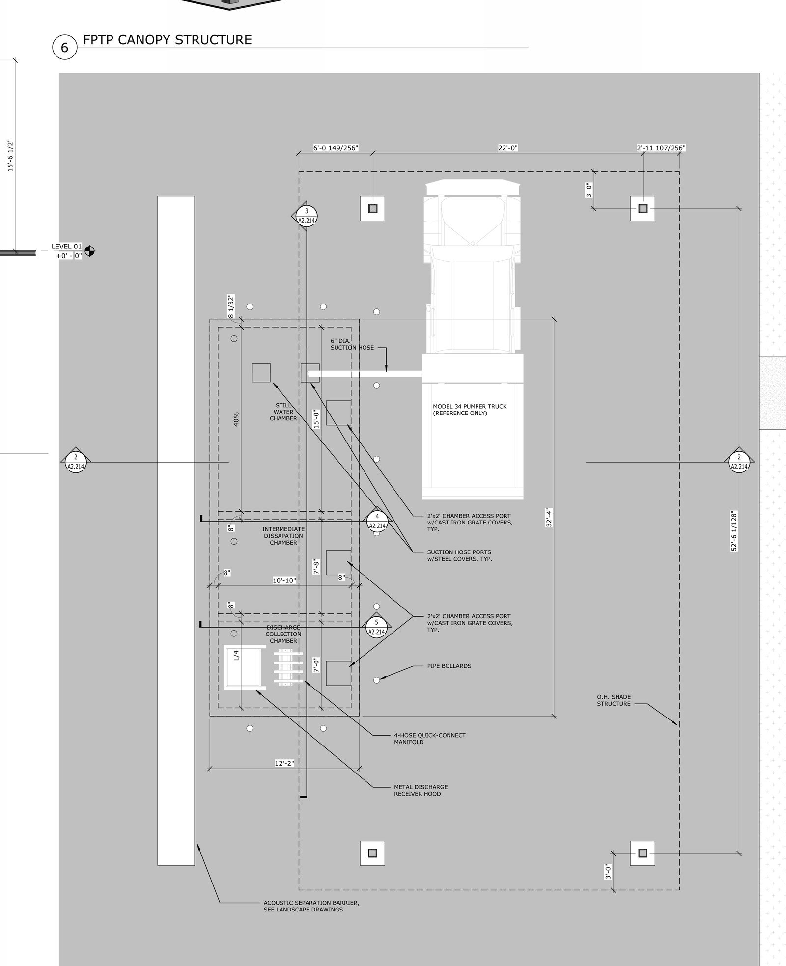
Reference drawing

A2.214 · Fire Pump Test Pit Plan

Original plan excerpt from the provided 50% CD drawing. Use this as the geometric reference while reviewing the reconstructed 3D model and live calculations above.
Open full image ↗
A2.214 fire pump test pit plan excerpt showing the three-chamber pit, Model 34 reference truck, suction hose, manifold, receiver hood, access ports and canopy columns
A2.214 plan excerpt · provided project drawing · reference image only. The interactive 3D model above is a reconstructed analytical visualization, not a replacement for the contract drawing.
Reviewed geometry basis

A2.214-derived research model

The 3D model is reconstructed from the reviewed dimensions and callouts shown on the A2.214 reference plan above: 31'-0" inside length, 10'-10" inside width, 7'-0" discharge chamber, 7'-8" dissipation chamber, 15'-0" still-water chamber, two 8" baffles, dual 2'×2' and dual 3'×3' submerged openings, 8'-0" baseline water depth, 6'-0" baseline static lift, and 3'-0" baseline strainer submergence.
PUBLIC REVIEW MODEL · GEOMETRY-BASED · NOT A CONSTRUCTION DOCUMENT · NOT CFD
Design review focus

What should be resolved before design advances

PRIORITY 1
Confirm the governing apparatus schedule and maximum test flow.

The Model 34 reference and the 1,000 / 1,500 / 2,000 GPM calculation basis are not internally aligned. Geometry changes should follow this decision, not precede it.

PRIORITY 2
Correct usable-volume calculations.

The gross 31 ft water prism counts the two concrete baffles as water. The current 8 ft condition is approximately 19,363 gal before optional sump volume.

HIGH
Define suction configuration and test instrumentation.

Confirm simultaneous hose count/size, manufacturer-based suction losses, vortex control, and the method used to measure and document actual test flow.

STUDY
Reframe de-aeration around residence time and return-water behavior.

Baffle opening velocity alone cannot prove complete de-aeration. Evaluate stagger, jet dissipation, above-water air entrainment and suction separation.

COORD.
Complete operational and structural coordination.

Water-level indication, make-up, overflow, drain-down, backflow protection, maintenance access, liquid-tight concrete, buoyancy and vehicle loading should be confirmed in the applicable disciplines.

Scientific communication boundary

Calculated

Usable volume, gal/GPM, static lift, nominal hose velocity, baffle opening velocity, chamber residence time and pit turnover are directly recomputed from the selected inputs.

Engineering screening

Suction performance and vortex/submergence are shown only as prompts for engineering verification. Manufacturer curves, actual strainer geometry and apparatus configuration are needed for a defensible final result.

Illustrative visualization

Particles, bubbles, return jets and vortex graphics explain flow mechanisms qualitatively. They are not finite-volume CFD, measured velocity fields or stamped engineering analysis.

Calculation & representation notes. Primary thresholds follow the supplied Scott review direction. The velocity-area relationship is Q = A × V̄; see USGS: How Streamflow is Measured. Air screening is a transparent reduced-order comparison (rise time vs. credited Chamber 2 residence time), not a validated design method or a de-aeration efficiency prediction. Animation is not used to calculate a PASS. Bubble glyphs denote mechanisms; carryover glyphs indicate screening risk, not a measured gas concentration. Baffle lower opening sizes and clear chamber lengths follow the supplied A2.214 drawing; vent-slot, slab, equipment and access details remain schematic. Dimensions and volume calculations exclude sump and hardware displacement unless stated. Public review prototype — not construction documentation.